Oh, how one project leads to another.
After restoring iDRAC access for Herbert, the primary production server, the next goal was to move forward with getting Proxmox reinstalled and the rebuild process underway. However, while updating the rack layout, switchport sheets, patching notes, and connection labels, I realized the rack itself needed some cleanup before I started putting services back into production.
The original plan was to replace the power supply cables for both servers with properly sized 14 AWG cables and continue rebuilding from there. While preparing for that, I realized I was going to need another PDU because I was moving from one PSU cable to two across 3 devices, and I didn’t have enough available outlets for that change. Fortunately, I remembered that I had previously acquired two APC AP7750 Automatic Transfer Switches during an end-of-life cleanup at my previous employer, which, naturally, is where one thing turned into something else, and the rabbit hole began.
Instead of buying another PDU, I decided to rack both ATS units and use them to improve the power redundancy inside the rack.
Initial Placement and Fitment#
I gave both transfer switches a basic wipe-down and started test-fitting them in the rack. My first plan was to install them in rack spaces 1 and 3, directly behind both APC UPS units. That placement seemed logical at first because it kept the ATS units close to their power sources and helped keep the lower part of the rack focused on power distribution.
After a quick test fit, I noticed that the factory cable trays on the ATS units slightly interfered with the UPS power cabling and made the space tighter than I wanted. The trays were functional, but they were just large enough to make the install feel cramped.
Rather than forcing that layout as a quirk of the installation location, I put the racking both ATS units on hold and spent some time designing a smaller replacement bracket that could be installed in place of the original cable tray.
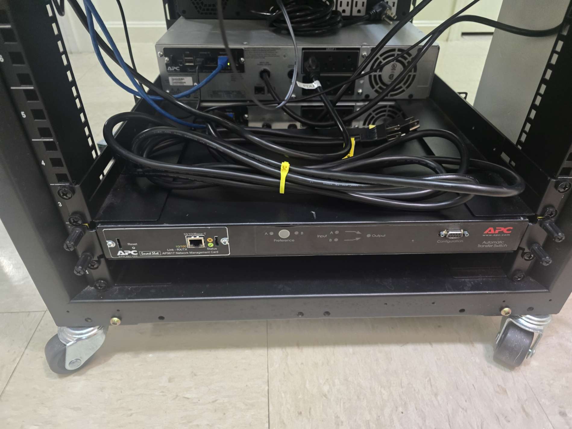
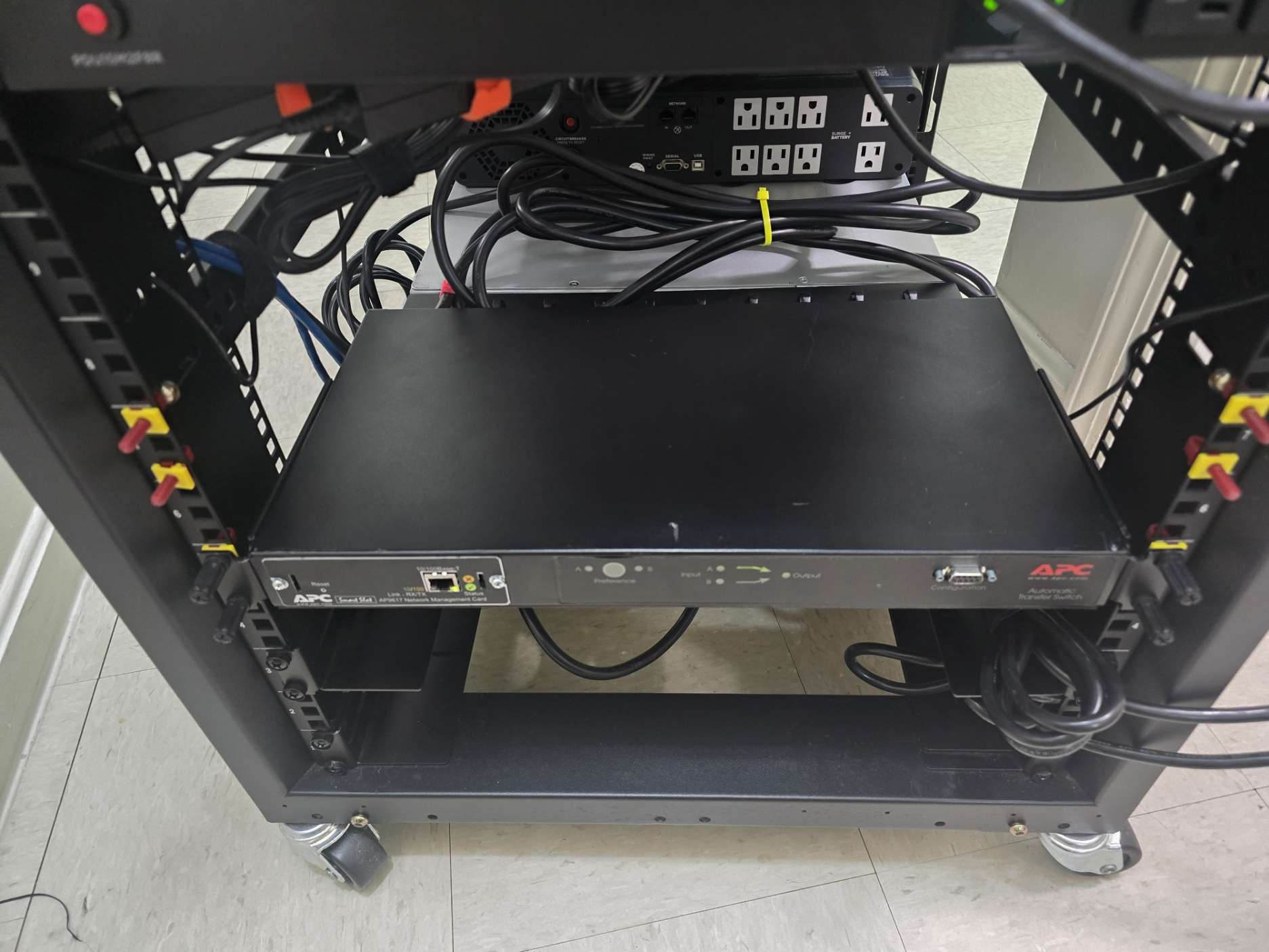
Modeling a Replacement Bracket#
MakerWorld link: APC AP7750 ATS Modified Cable Tray
This turned into a small side project of its own. I spent about a day and a half modeling, printing, testing, and adjusting a replacement bracket. The goal was to reduce the width and depth of the original cable tray while still providing enough cable support behind the ATS.
During that process, I found that the mounting hole spacing was not perfectly uniform between both transfer switches. The bracket still fit well enough to be usable after some revisions that ended up making the whole thing look sort of like a Frankenstein project. I think a slotted design for the hole spacing would have been a better fit to account for the variation between vertical hole spacing, but alas, hindsight is 2020.
With both replacement brackets printed and installed, I went back to installing the transfer switches.
Then, of course, I changed my mind.
Even with the shortened bracket, I still was not happy with the amount of working room between the transfer switches and the UPS units when the power cables for all other devices were installed. Since the entire point of the smaller bracket was to improve clearance, I decided the answer was to admit defeat and move the ATS units higher in the rack instead of trying to force the lower placement to work. Doing this was primarily to preserve what sanity I had left at this point, as well as give future-me a bit of consideration to avoid further headaches later down the road.
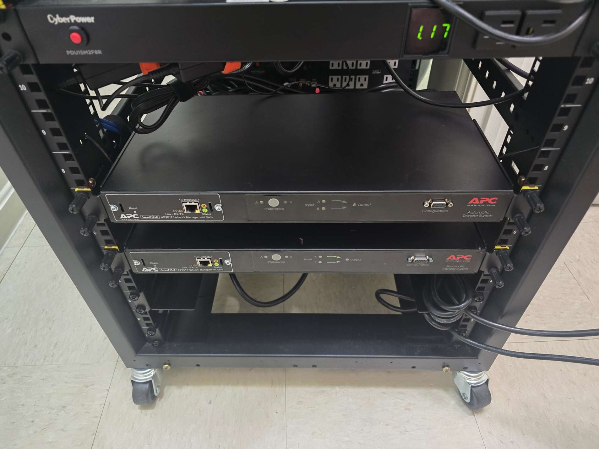
I relocated the transfer switches to rack spaces 5 and 8. With the ATS units installed higher, there was enough room to work with, and the smaller replacement brackets were no longer necessary. I reinstalled the original factory cable trays and treated the printed brackets as a useful learning exercise instead. Even though the custom brackets didn’t end up being used in the final installation, I don’t consider that time spent as being totally wasted. It gave me more practice with modeling, print settings, iterative design, installation planning, and fitment testing. It also led to some needed printer maintenance during the process, as I had to complete a printer teardown to diagnose and clear a major clog (almost 10 years of being a mold technician paid off here to think from the perspective of the heated plastic).
Cabling Cleanup#
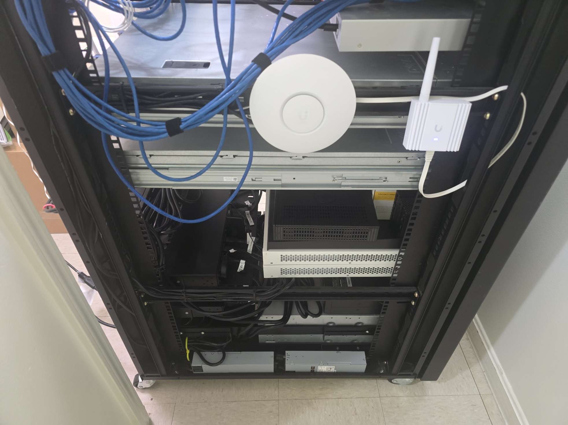
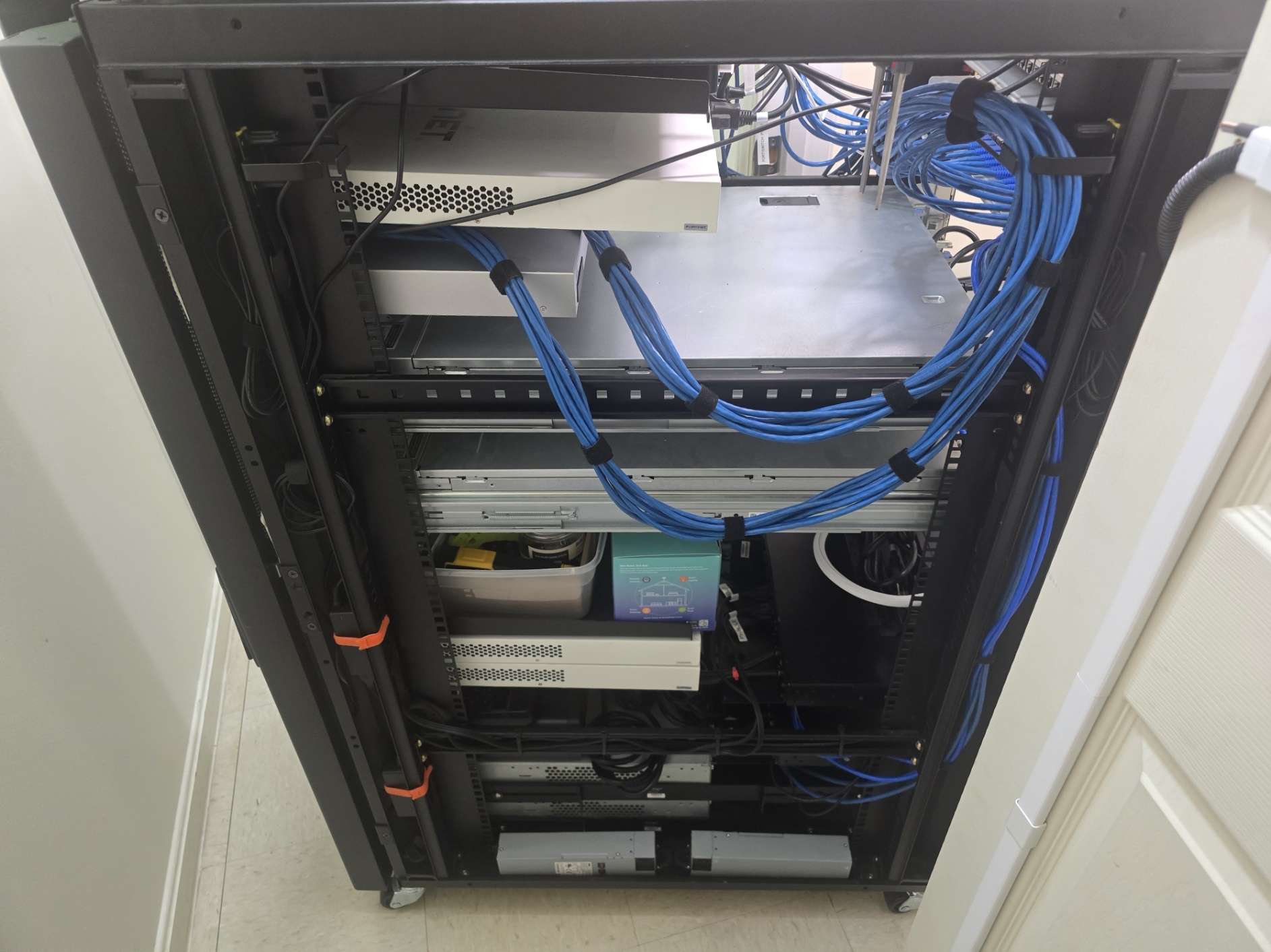
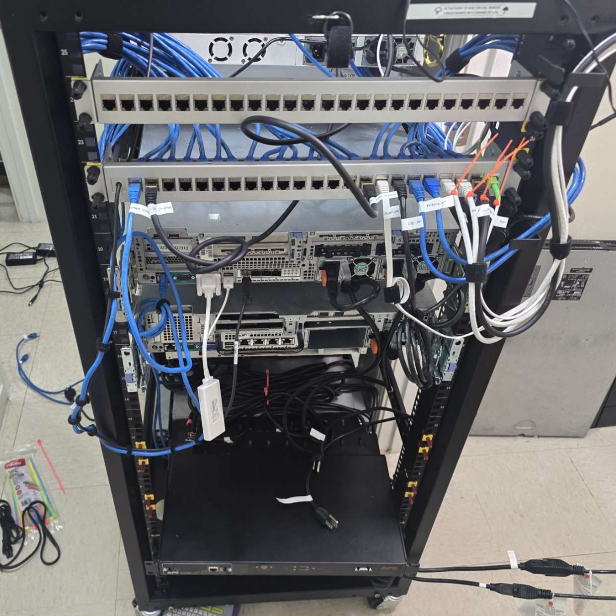
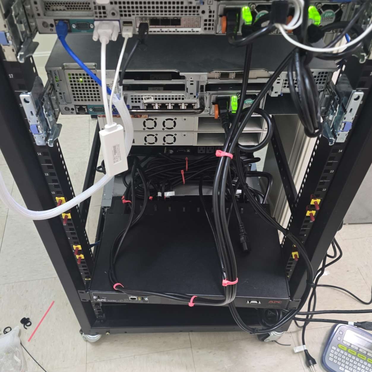
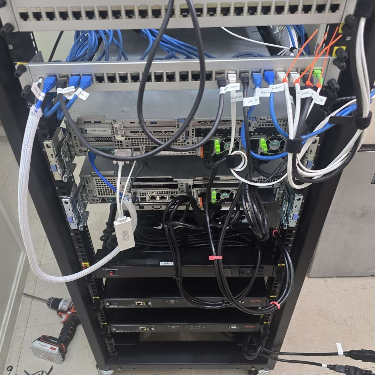
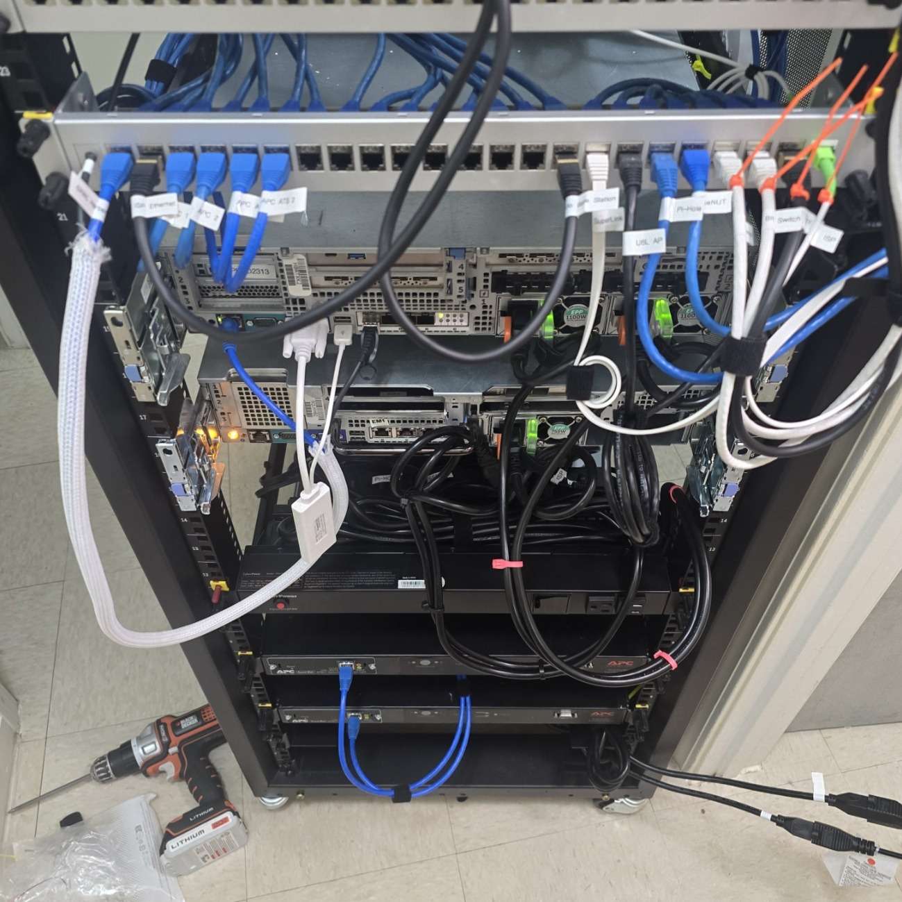
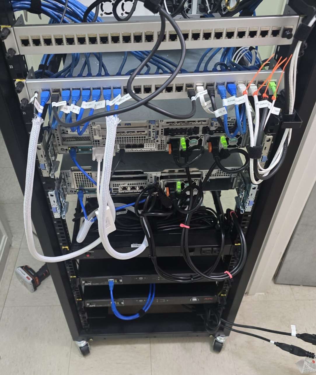
With the final ATS placement decided, I reworked the power cabling for the entire rack.
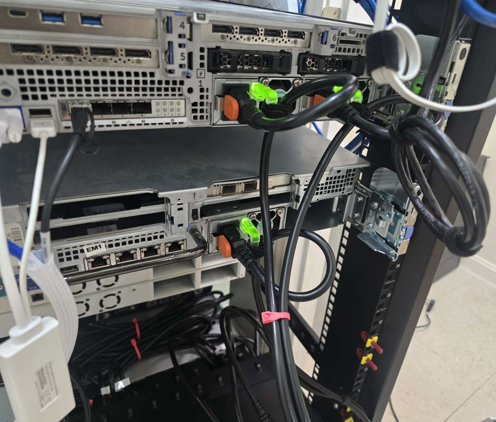
I also installed redundant power supplies in Herbert, which had been running with a single 1100 W power supply for far too long. That server had been reporting the missing redundant PSU condition for the better part of a year, so this was a good opportunity to finally correct it. I then re-ran power cabling for the learning server, learn.lab, so it will be ready when the rebuild reaches that stage.
Power was routed primarily along one side of the rack to avoid unnecessary overlap with critical network cabling. For the servers, I grouped the redundant PSU cables together in pairs and routed them cleanly down to the ATS units. I also made sure there was enough slack for both servers to slide out on their rails during maintenance without pulling or snagging cables, something I learned very early on during maintenance and upgrade routines.
ATS Layout and Power Strategy#
The current layout uses both ATS units with both UPS units connected as inputs, but each ATS has a preferred source.
ATS 1is used for the servers, andprefers UPS 1.ATS 2is used for critical network and infrastructure equipment, andprefers UPS 2.
I understand that the benefit of redundancy is lost in some capacity here, as we would typically favor a sort of circular model where every redundant power supply is fed by another point of fault tolerance. However, this is a home lab, and I get to make the rules.
The idea is not to treat every piece of equipment as equally important during an outage. The servers provide useful services such as Plex, Nextcloud, lab workloads, and other self-hosted applications, but they are not the highest priority during a power-loss event by any means. Rather, the more important goal is keeping core network infrastructure online for as long as reasonably possible. In a severe weather or extended outage scenario, DNS, routing, switching, and basic network access are more important than having access to local movies and television shows (although you could argue that with the children).
This is my thought process behind how this is handled, at least initially. This may change at some point in the future, but this approach was how I wanted to handle it last year as well.
- Equipment with redundant power supplies gets input redundancy during normal operation.
- Server workloads should gracefully shut down during an extended outage.
- Critical networking should remain online as long as possible.
- UPS 1 and UPS 2 should serve different priorities instead of simply sharing the same load equally.
- During normal operation, the ATS units provide additional input fault tolerance. If one UPS, power cable, or input path has an issue, the ATS can transfer to the alternate source.
- During a power outage (classified as when both UPS 1 and UPS 2 report they have lost power from mains), the servers on ATS 1 should shut down gracefully from UPS 1. Once that load is removed, the remaining battery capacity is then offered to what I consider our critical infrastructure on ATS 2, and can deplete UPS 2 first before transferring to UPS 1 when needed.
This is not a perfect high-availability power design, but it’s a practical improvement for the rack and is better than having the server workload take out all UPS units in 10 minutes or less.
Network and VLAN Updates#
I also created a new VLAN for the learning server in anticipation of its setup later, VLAN 30.
I updated the FortiSwitch port profiles and connected both the iDRAC and standard networking interfaces for the server. I also sleeved the network cables for both servers in a similar way to the PSU cable groups.
Firewall rules were updated so the new VLAN follows the same general security posture as the rest of the lab.
Documentation#
After the physical and network changes were complete, I updated the rack layout, switchport documentation, and patch panel sheets again (this is something that will never be finalized)
Documentation continues to be one of the most important parts of this rebuild. The physical rack layout, VLAN assignments, switchport profiles, patching notes, and firewall behavior all need to stay aligned throughout, as it’s worked on, so I can avoid small change creep that will ruin me when I attempt to recall the changes I’ve made later.
Remaining Work#
The ATS units are now physically installed and cabled, but the management cards still need to be reset and reconfigured.
Both units have AP9617 Network Management Cards installed. After some research, these older NMC1 cards do not use the same reset behavior as newer APC management cards, so the reset process will likely require a serial connection. I still need to confirm whether my existing USB-to-serial adapter and cable setup will work or whether I need the correct APC serial cable with the proper pinout.
This started as a simple power-cable cleanup task, but snow-balled into a more complete rack power and cabling improvement. In typical home lab fashion, each step exposes another area that can be cleaned up, documented, or improved, and it’s difficult to not want to do everything all at once.
Reply by Email