With the main Proxmox server rebuilt, storage configured, SMB sharing online, and baseline backup routines in place, the next major goal was improving DNS resiliency.
Up to this point, DNS had been running from an interim Pi-hole instance on a Dell Wyse 5070 thin client. That worked well enough as a temporary solution, but it was still a single device carrying the DNS path for the entire network. If that one thin client failed, DNS would fail with it. If I eventually hosted DNS only on the main server, DNS would also disappear any time the server shut down during a power outage.
That does not fit the direction I want this rebuild to take.
The goal for this phase was to move toward a low-power infrastructure layer using Dell Wyse 5070 thin clients as Proxmox nodes. These systems are not meant to compete with the main server for heavy workloads, but they are perfect for small critical services like DNS. By moving Pi-hole onto two separate Wyse nodes, DNS can remain online even if the main server is offline.
Preparing the First Wyse Node#
The first system I rebuilt was the old WyseNUT server, which is now wyse01.
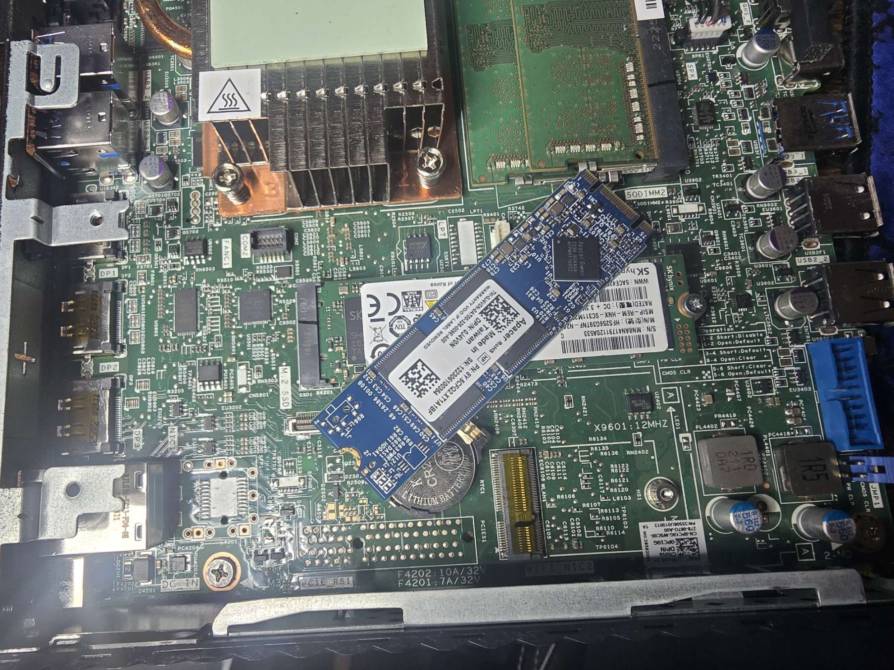
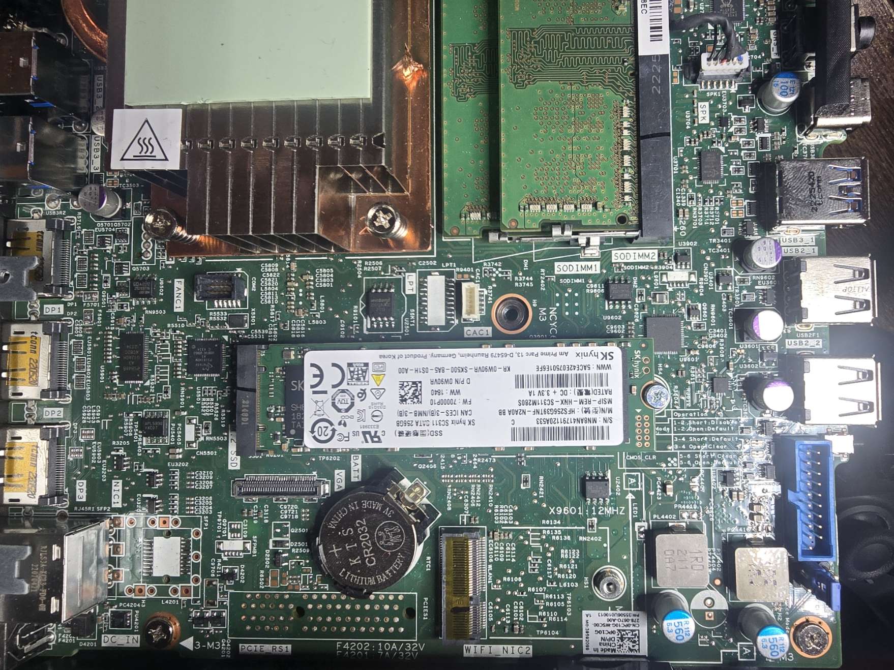
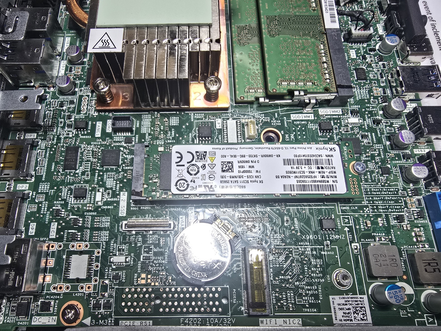
I pulled the existing drive from the Dell Wyse 5070 and replaced it with a 256 GB drive. The original 64 GB module was enough for a minimal Linux installation, but I wanted more breathing room for Proxmox, containers, updates, Docker, logs, and future service growth.
My first plan was to install Proxmox at the rack using a projector, but that plan fell apart quickly as the projector does not have DisplayPort, and I did not have a DisplayPort-to-HDMI adapter handy. Since the Wyse 5070 does not have HDMI or VGA output, I moved the system to my workstation desk instead and used an extended Ethernet cable back to the rack.
The Wyse was connected directly to port10 on the FortiSwitch. For the initial install, that port was still placed on VLAN 10 so the installer could come online cleanly on the Management network.
I booted from my Ventoy USB and started the Proxmox VE 9.2 installer. The first boot showed an expected prompt related to the drive being swapped, so I entered the Dell Wyse BIOS, cleaned up the old boot entries, and re-added Ventoy as a boot option. These machines use Fireport as the default BIOS password when prompted for configuration changes.
During installation, I assigned the first Wyse node.
Hostname: wyse01.lab.shannonwetnight.com
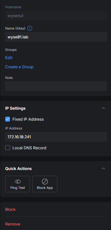
IP Address: 172.16.10.241/24
Gateway: 172.16.10.1
DNS Server: 172.16.10.1
This follows the same management addressing pattern as the main Proxmox node.
home.lab   172.16.10.240
wyse01.lab 172.16.10.241
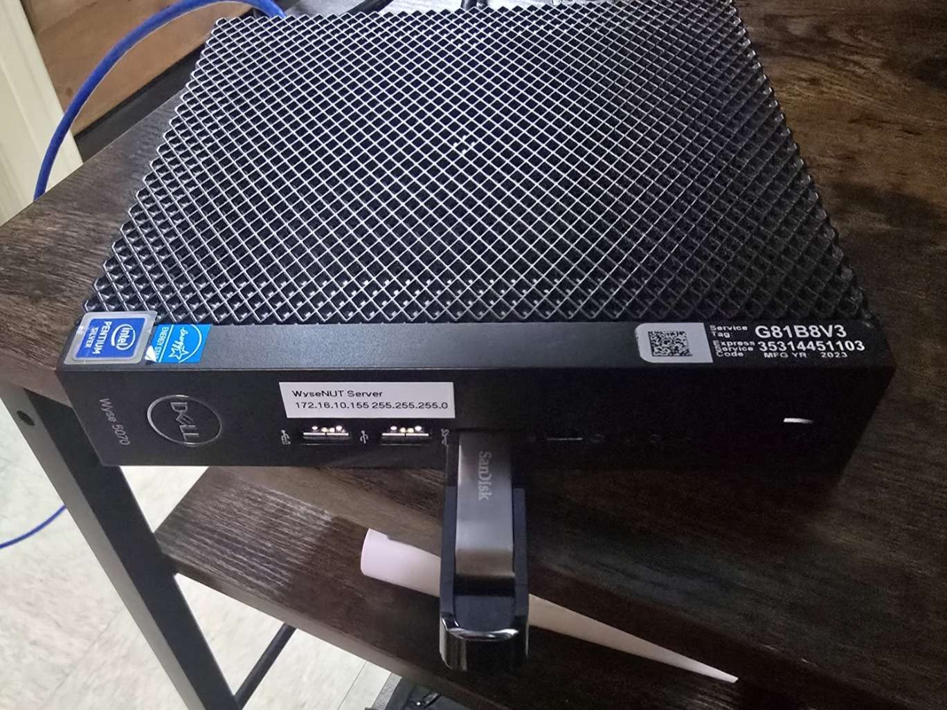
After the installer finished, I powered the system down, moved it back into the rack, and updated the physical label to include the new hostname and IP address.
wyse01.lab
172.16.10.241
255.255.255.0
I also updated my switchport layout and device tracking sheets so the documentation matched the new physical and network layout.
Initial Proxmox Configuration#
Once wyse01 was reachable through the web interface, I used the same post-install process from the main server rebuild. I added the Proxmox no-subscription repository, disabled the enterprise repositories, then updated and rebooted the host.
After that, I checked the hostname and local host resolution.
root@wyse01:~# hostname
wyse01

root@wyse01:~# hostname -f
wyse01.lab.shannonwetnight.com
The local /etc/hosts file initially contained only the local node entry.
127.0.0.1 localhost.localdomain localhost
172.16.10.241 wyse01.lab.shannonwetnight.com wyse01
Before joining the node to the Proxmox cluster, I added host entries on both systems so the main server and the Wyse node could resolve each other by hostname and FQDN.
On wyse01, I added home.lab.
127.0.0.1 localhost.localdomain localhost
172.16.10.241 wyse01.lab.shannonwetnight.com wyse01
172.16.10.240 home.lab.shannonwetnight.com home
On home.lab, I added wyse01.lab.
127.0.0.1 localhost.localdomain localhost
172.16.10.240 home.lab.shannonwetnight.com home
172.16.10.241 wyse01.lab.shannonwetnight.com wyse01
I validated name resolution in both directions. From wyse01, I confirmed that it could reach the main Proxmox node.
ping -c 4 home.lab.shannonwetnight.com
ping -c 4 home
From home.lab, I confirmed that it could reach the Wyse node.
ping -c 4 wyse01.lab.shannonwetnight.com
ping -c 4 wyse01
Creating the Proxmox Cluster#
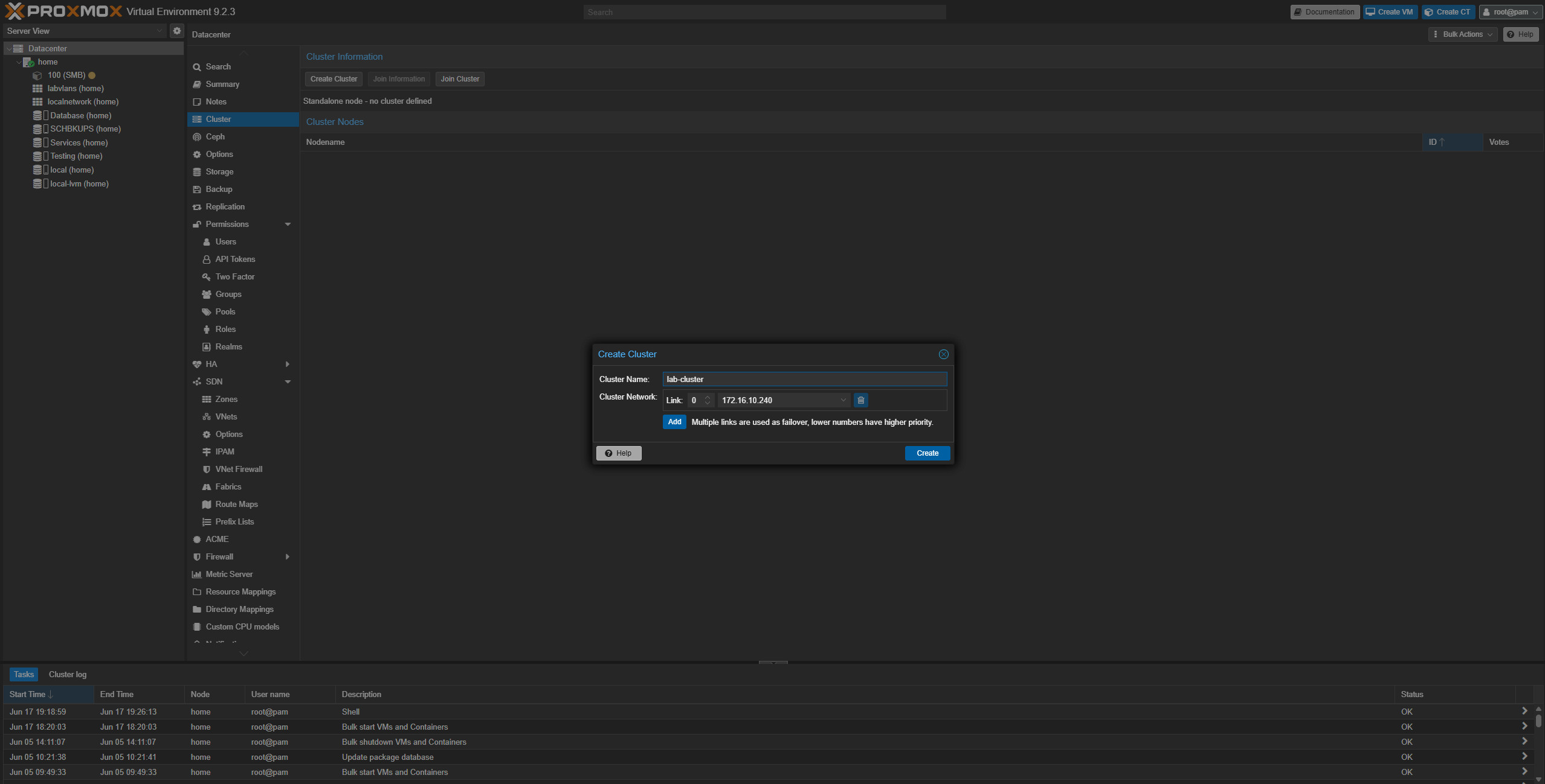
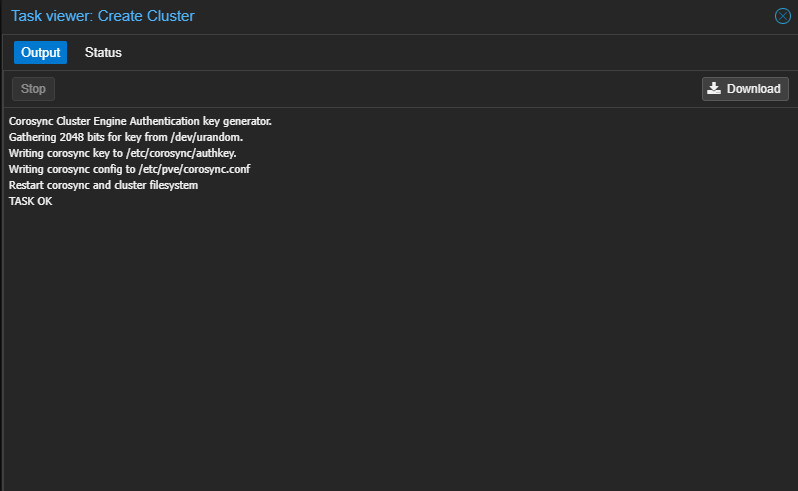
With name resolution working, I created a Proxmox cluster from the main home.lab node.
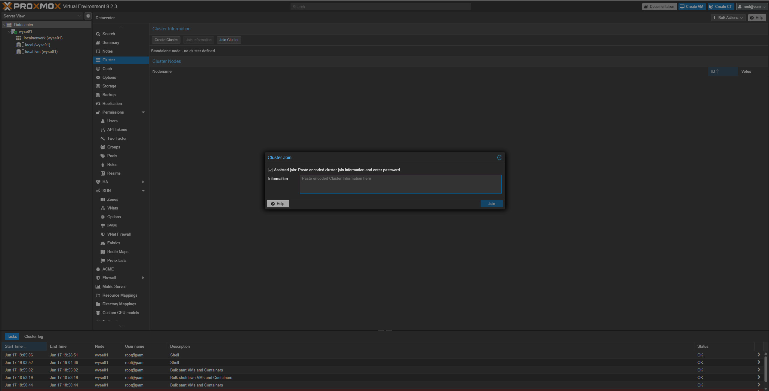
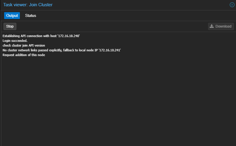
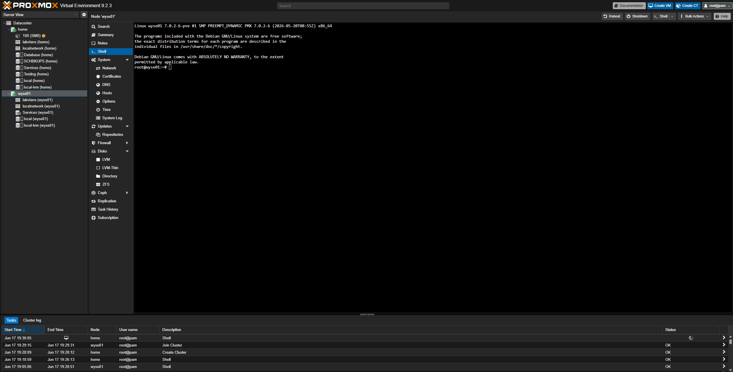
Cluster name: lab-clusterAfter creating the cluster, I copied the cluster join information from home.lab, opened the cluster panel on wyse01, pasted the join information, enabled assisted join, and entered the main host password.
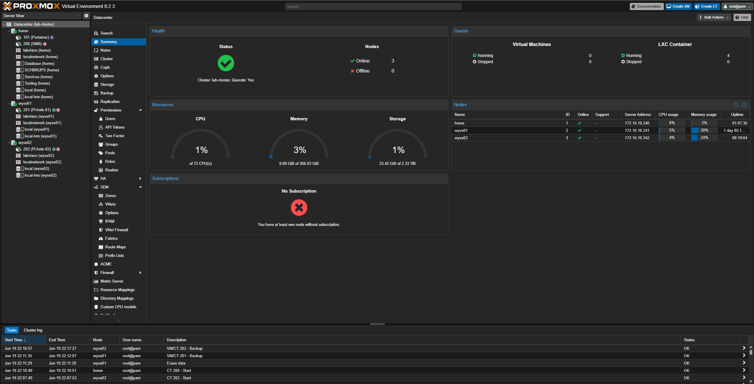
Once the join completed, wyse01 appeared as a node under the cluster.
At this point, the cluster had two nodes:
home
wyse01
This is not the final cluster layout, but it was enough to move forward with the first Wyse node. A two-node cluster is not ideal long-term because quorum depends on both nodes being online, but the plan was already to add another Wyse node shortly after.
Applying the SDN Configuration#
The main Proxmox server was already using the SDN design created earlier in the rebuild. The important part of that design is that the Proxmox host management interface lives on the SDN-created mgmt10 network instead of directly on vmbr0 or a manually created vmbr0.10 interface.
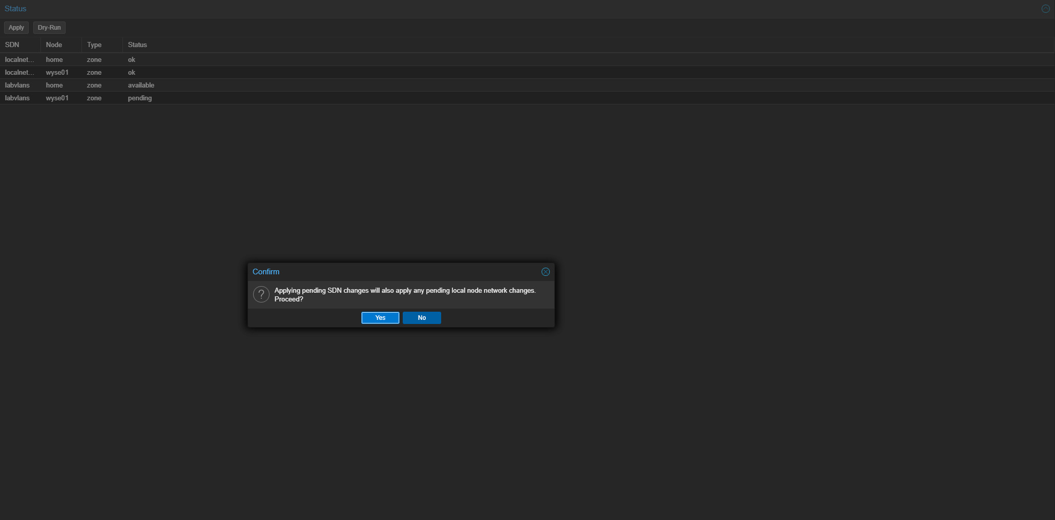
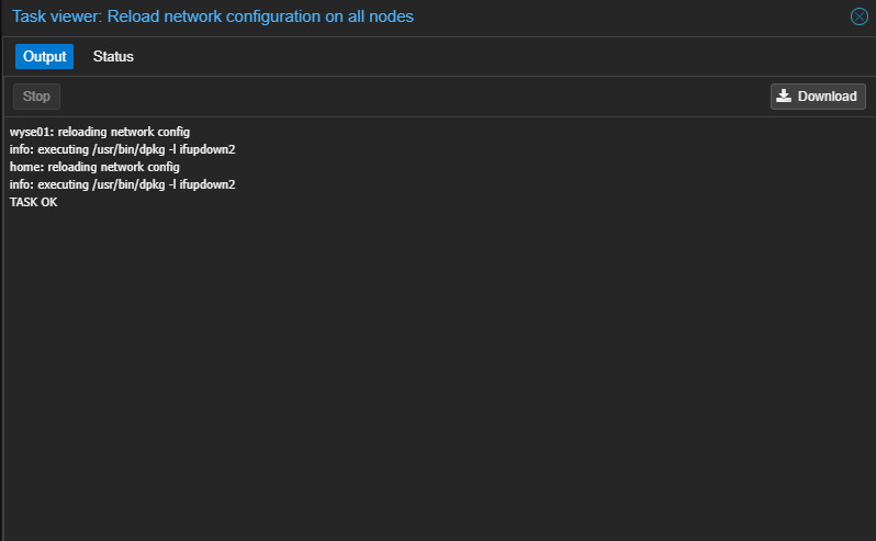
After wyse01 joined the cluster, the SDN configuration did not immediately exist locally in the generated interface file. To correct this, I re-applied the SDN configuration.
After applying the SDN configuration, the generated SDN file appeared properly in /etc/network/interfaces.d/sdn.
Then I edited the main interface configuration on wyse01 so it matched the SDN-owned management model already used on home.lab.
auto lo
iface lo inet loopback

iface nic0 inet manual

auto vmbr0
iface vmbr0 inet manual
        bridge-ports nic0
        bridge-stp off
        bridge-fd 0

source /etc/network/interfaces.d/*

iface mgmt10 inet static
        address 172.16.10.241/24
        gateway 172.16.10.1
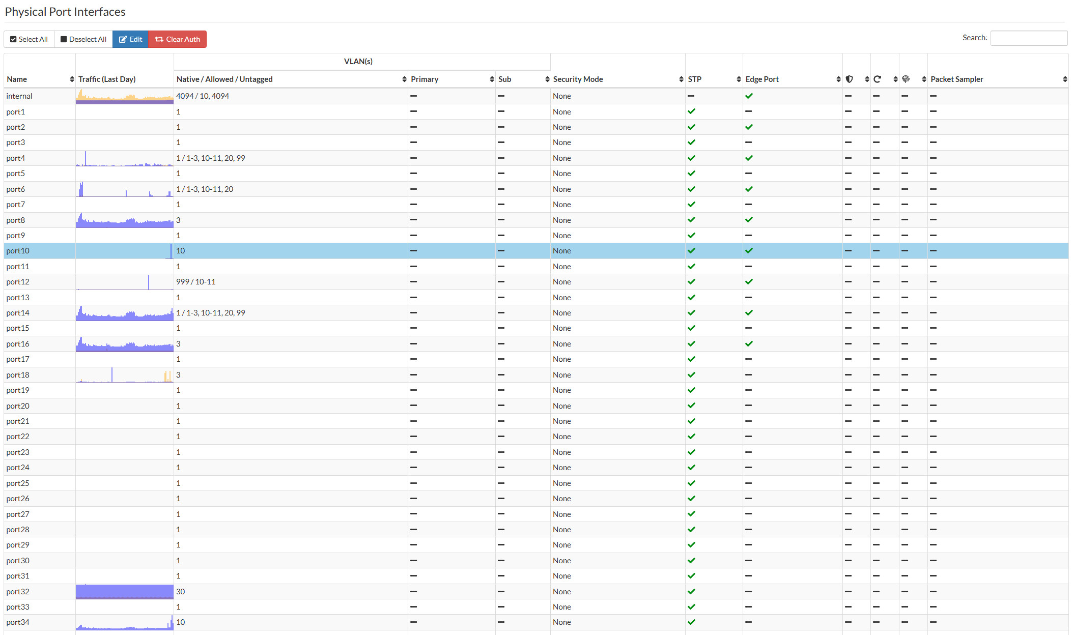
This keeps vmbr0 as a plain bridge with no IP address and places the Proxmox management IP directly on mgmt10. The switchport is intended to use a Blackhole-native VLAN with VLAN 10 and VLAN 11 tagged. Management traffic should be intentionally tagged as VLAN 10, and service traffic should be intentionally tagged as VLAN 11.
Native VLAN: 999
Allowed VLANs: 10-11
This sends untagged traffic nowhere useful while still allowing the Management and Services VLANs to pass as tagged traffic.
Avoiding a Lockout#
Unlike the main server, the Wyse thin clients do not have iDRAC or another out-of-band management path. If I broke the network configuration, I would need to physically access the system again. Because of that, I was careful with the order of operations.
First, I updated the Proxmox network configuration. Then I ran a quick ifreload-a.
After that, I updated the FortiSwitch port profile so the native VLAN was 999 and VLANs 10 and 11 were allowed as tagged networks.
After waiting for the network to recover, I was able to log back into wyse01 and validated the cluster status.
Cluster information
-------------------
Name:             lab-cluster
Config Version:   2
Transport:        knet
Secure auth:      on

Quorum information
------------------
Nodes:            2
Quorate:          Yes
The node list shows both nodes.
Nodeid      Votes Name
1           1     home
2           1     wyse01
I also confirmed the interface files.
auto lo
iface lo inet loopback

iface nic0 inet manual

auto vmbr0
iface vmbr0 inet manual
        bridge-ports nic0
        bridge-stp off
        bridge-fd 0

source /etc/network/interfaces.d/*

iface mgmt10 inet static
        address 172.16.10.241/24
        gateway 172.16.10.1
The generated SDN configuration exposes both networks.
At this point, wyse01 is installed, joined to the cluster, and aligned with the same SDN networking model as the main server.
Building the First New Pi-hole Instance#
With the node online, I moved on to DNS.
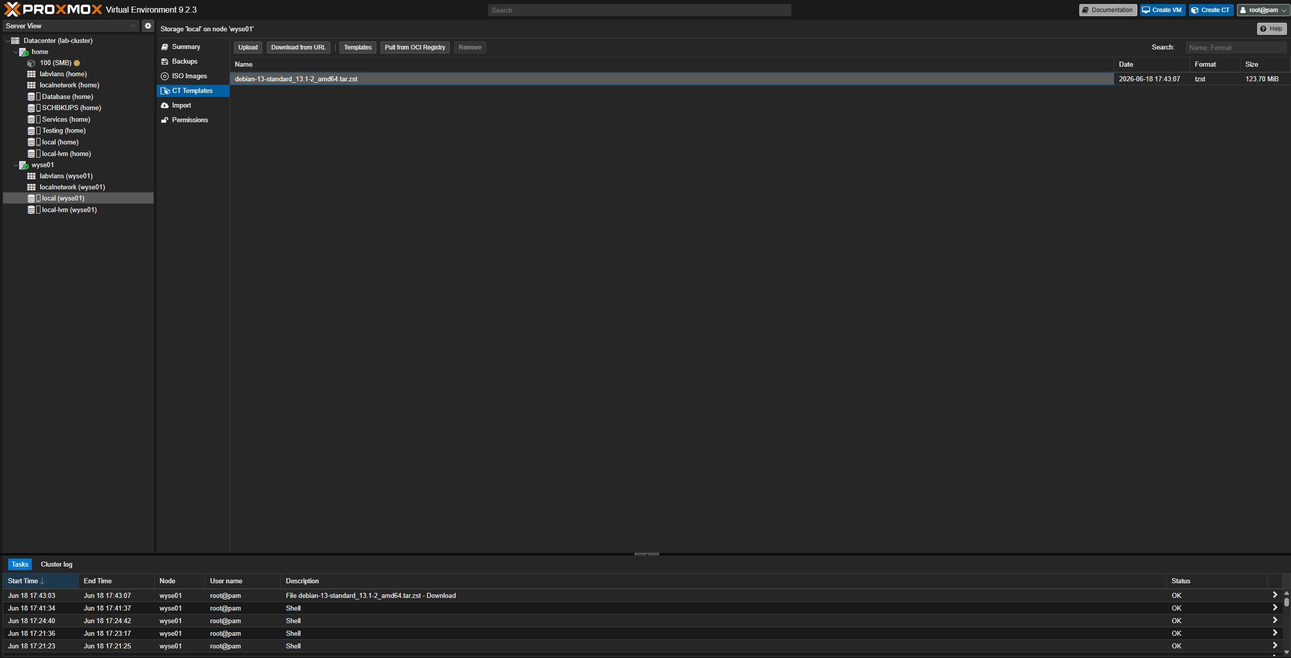
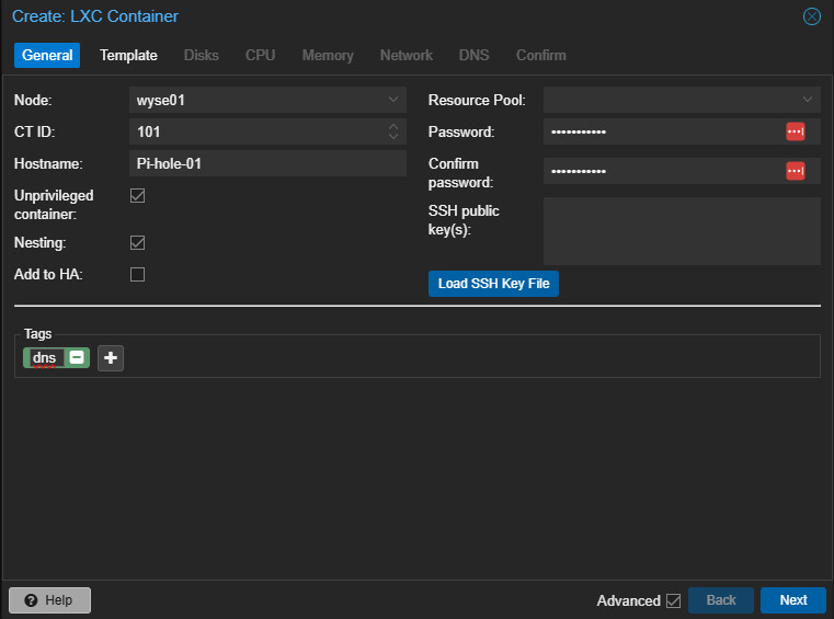
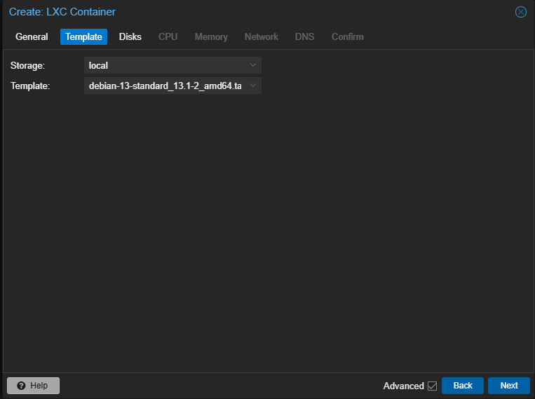
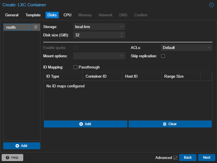
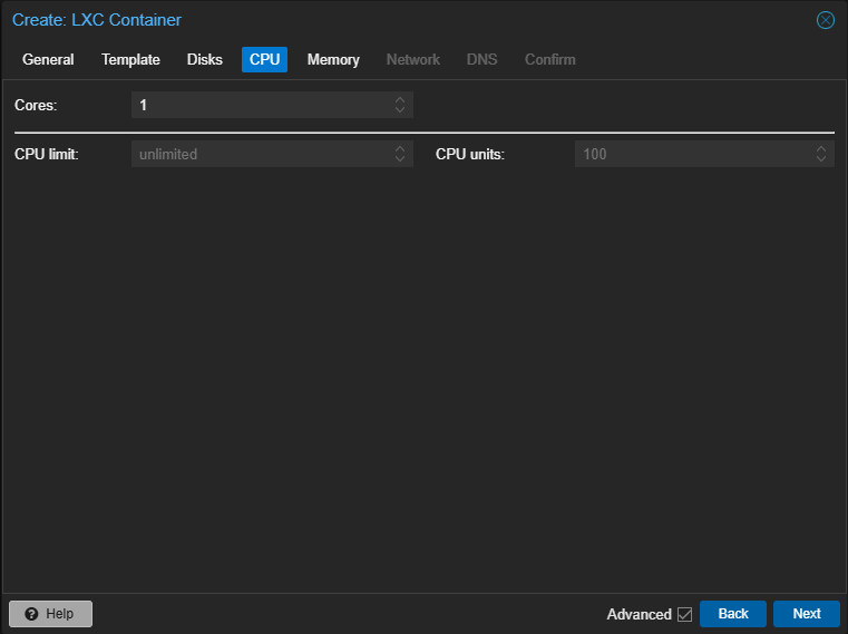
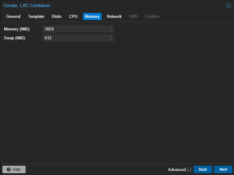
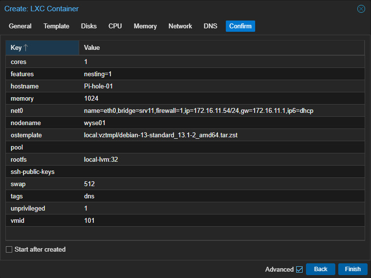
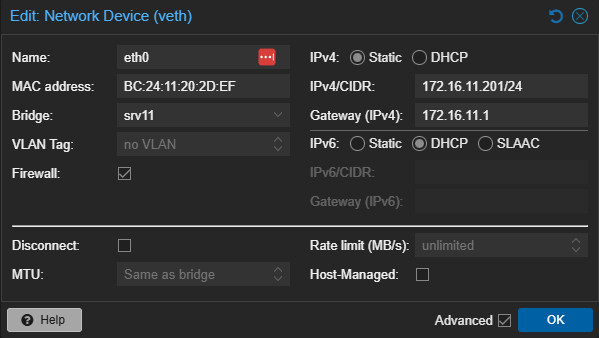
I added a Debian 13 container template to wyse01 and created a new container for the first Pi-hole instance.
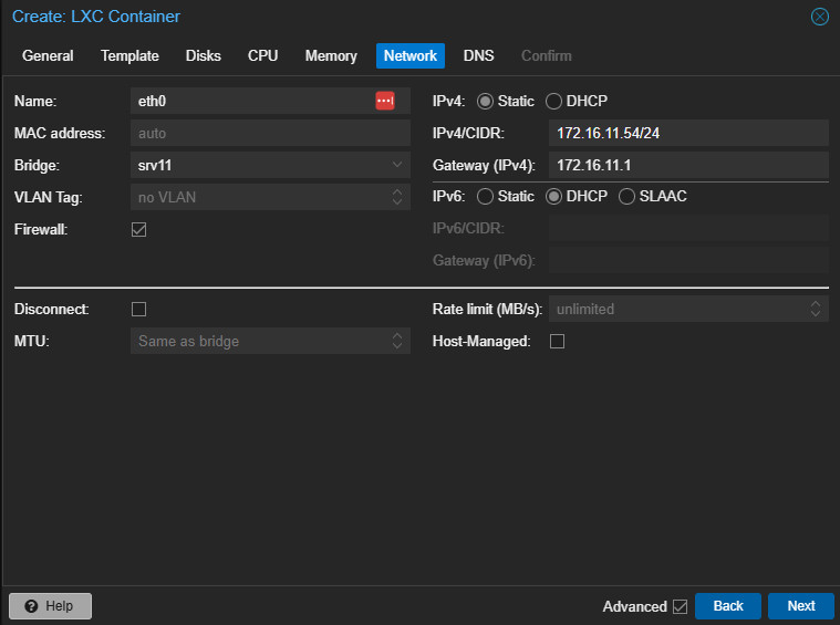
Container: Pi-hole-01
IP Address: 172.16.11.201/24
Network: Services VLAN
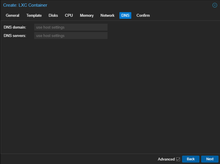
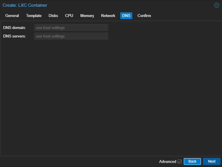
After the container came online, I logged in and ran updates. The first issue I hit was DNS resolution from inside the container. The container had been set to use the Proxmox host as its resolver, but the host lives on the Management VLAN. Since the Services VLAN is firewalled away from the Management VLAN, that DNS path did not work.
The fix was easy and could have been avoided during the initial container configuration. I simply changed the container nameserver to the Services gateway as it was still referencing the host, which it could not communicate with (intentional).
nameserver 172.16.11.1After that, updates worked normally. I installed Docker and Docker Compose using Docker’s Debian installation documentation. Originally, I was only going to deploy Pi-hole, but I decided this was also the right time to bring Portainer into the rebuilt environment.
Adding Portainer#
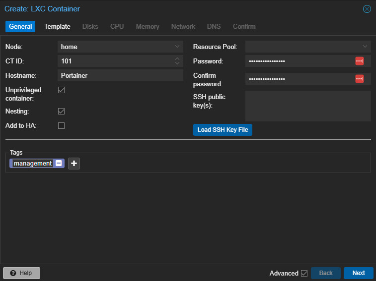
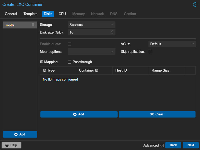
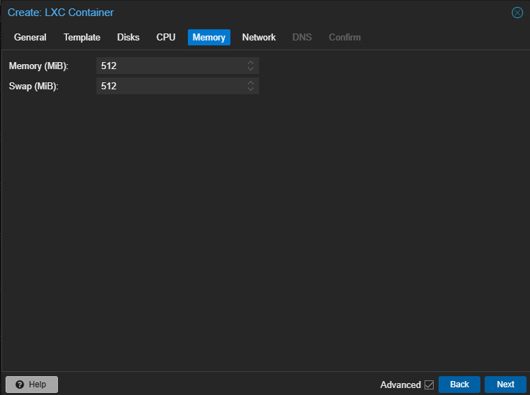
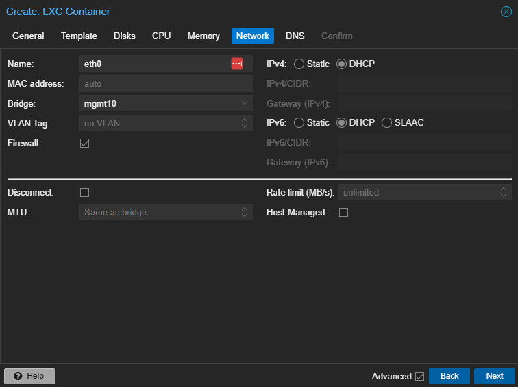
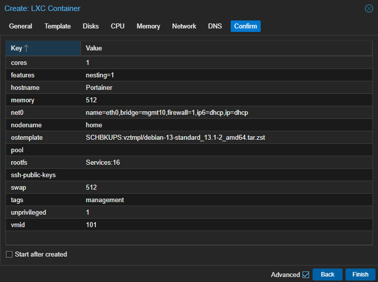
I created another Debian container on home.lab and installed Docker and Docker Compose there as well. This container became the Portainer management portal to replace the interim Portainer instance running in a VM on my workstation.
Container: Portainer
IP Address: 172.16.10.101
I intentionally placed Portainer on the Management network and kept the IP address aligned with the container ID scheme. And, at this point, I also adjusted my container ID scheme again.
100 range: Management
200 range: Services
300 range: Testing/Playground
Because of this change, I backed up the existing SMB container, destroyed it, changed the UniFi IP assignment to 172.16.11.200, and recreated the container using ID 200 instead of 100. That keeps SMB in the Services range where it belongs.
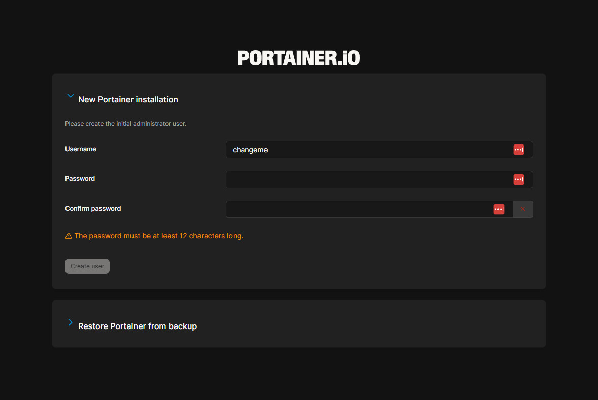
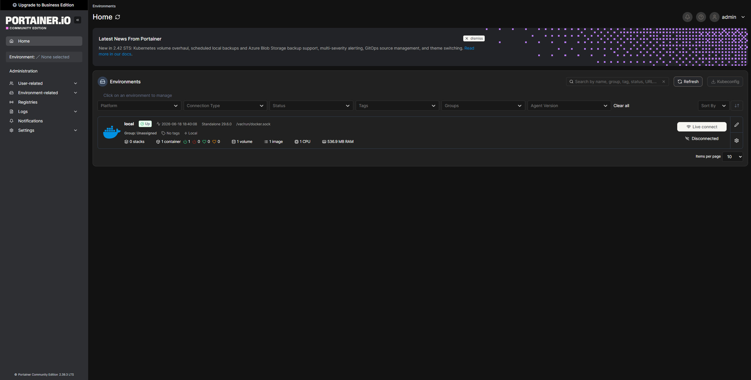
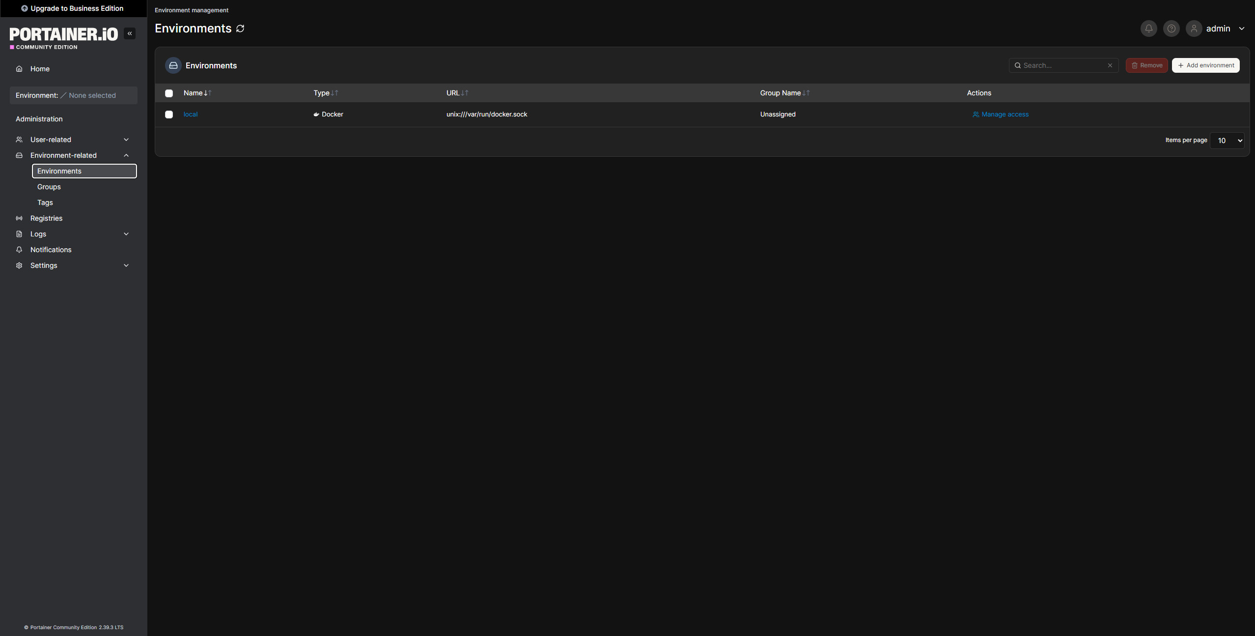
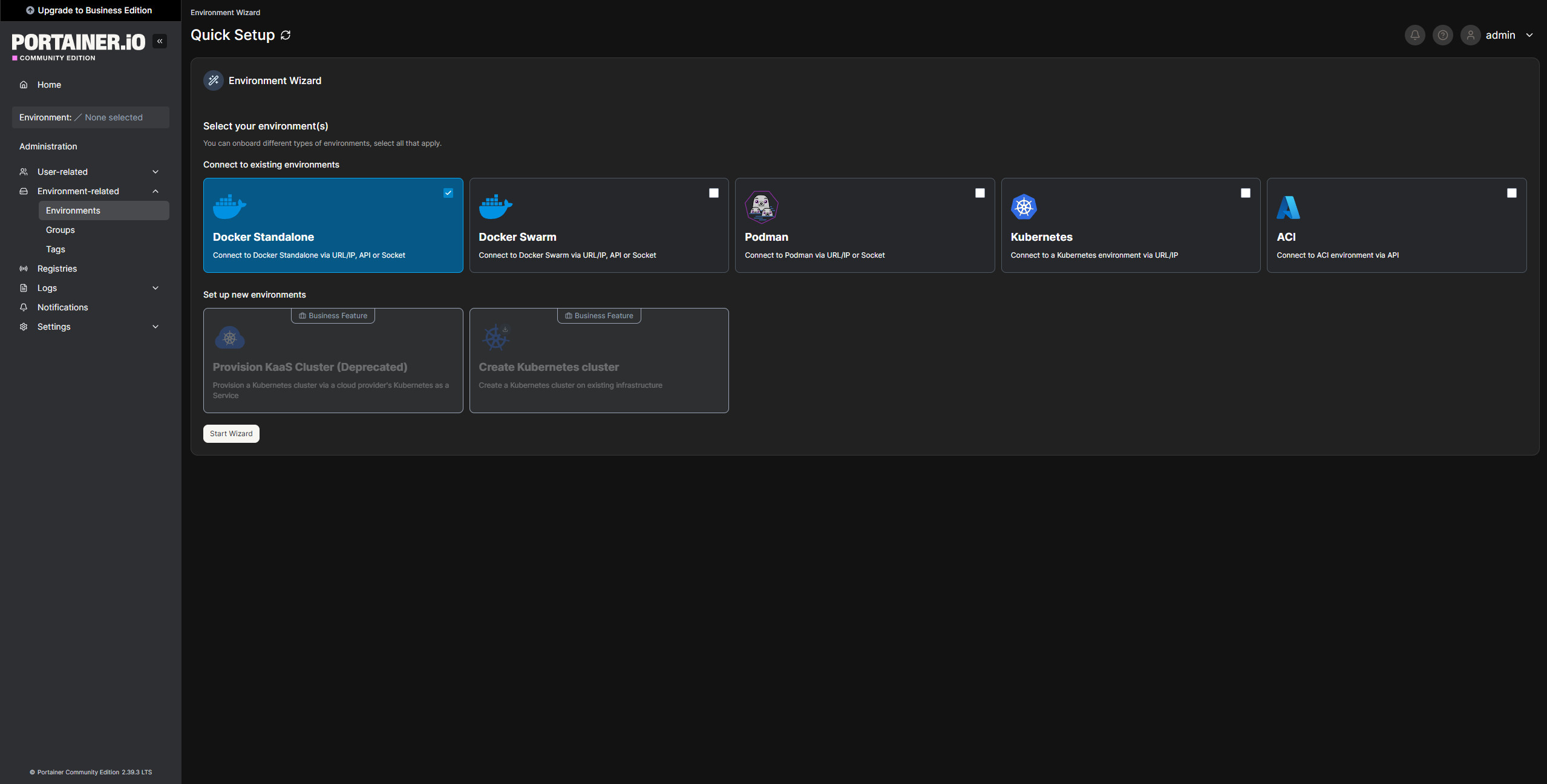
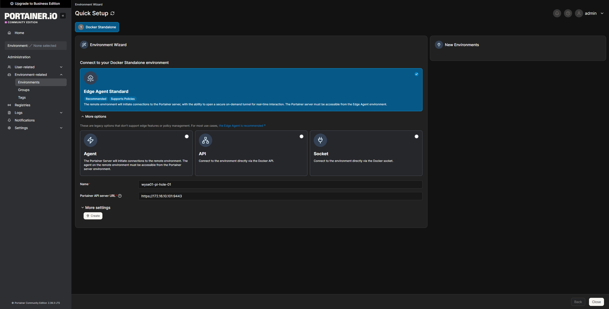
After Portainer was installed, I created the initial admin account and added an Edge Agent environment for the Pi-hole container.
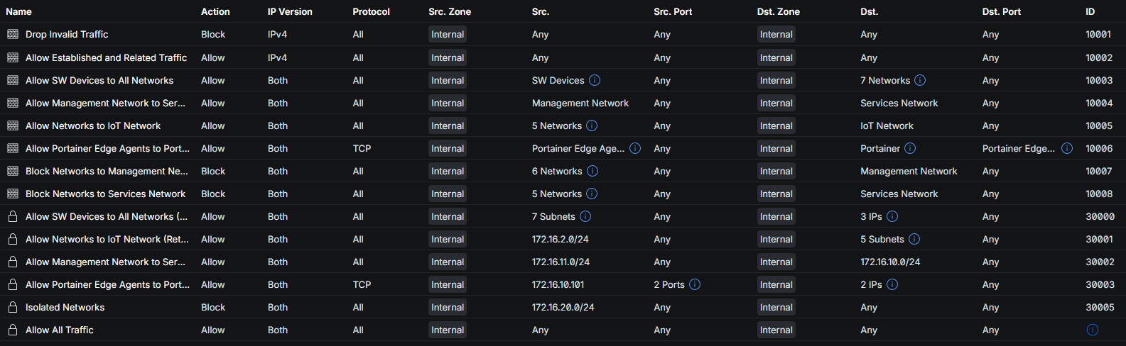
The first Edge Agent deployment did not join successfully, which made sense after looking at the network path. The Pi-hole container was on the Services VLAN, while Portainer was on the Management VLAN. The firewall rule blocking Services-to-Management traffic was doing exactly what it was supposed to do.
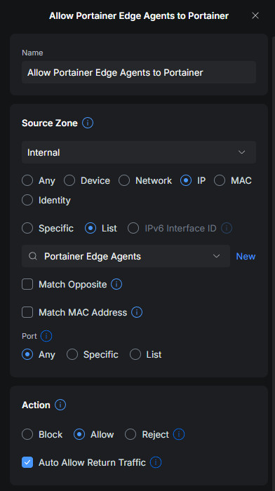
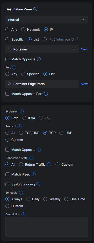
I added a specific firewall allow rule so Portainer Edge Agents could reach the Portainer management container. The rule needed to sit above the broader Services-to-Management block rule. I only allowed the ports Portainer was actually exposing, rather than traffic to any port (no need for that).
8000
9443
After the firewall rule was added, I redeployed the Edge Agent on Pi-hole-01, and it connected successfully.

Deploying Pi-hole Through Portainer#
Once the Edge Agent was connected, I created a Portainer stack for the first DNS server.
Stack name: wyse01-pi-hole-01The stack was connected to my GitHub repository containing the Pi-hole docker-compose.yaml file. This lets Portainer deploy the stack from version-controlled configuration instead of manually pasting Compose content into the UI.
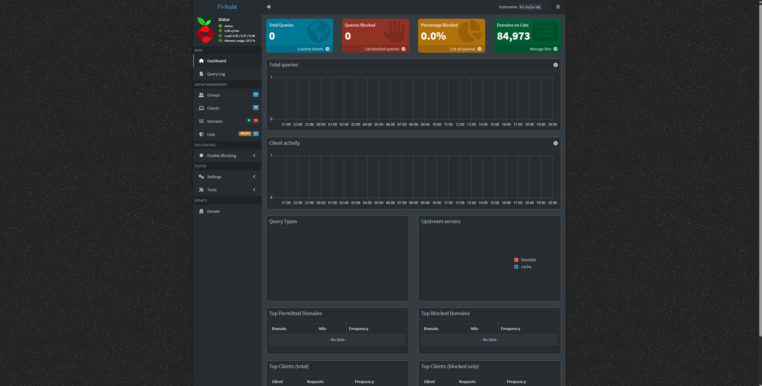
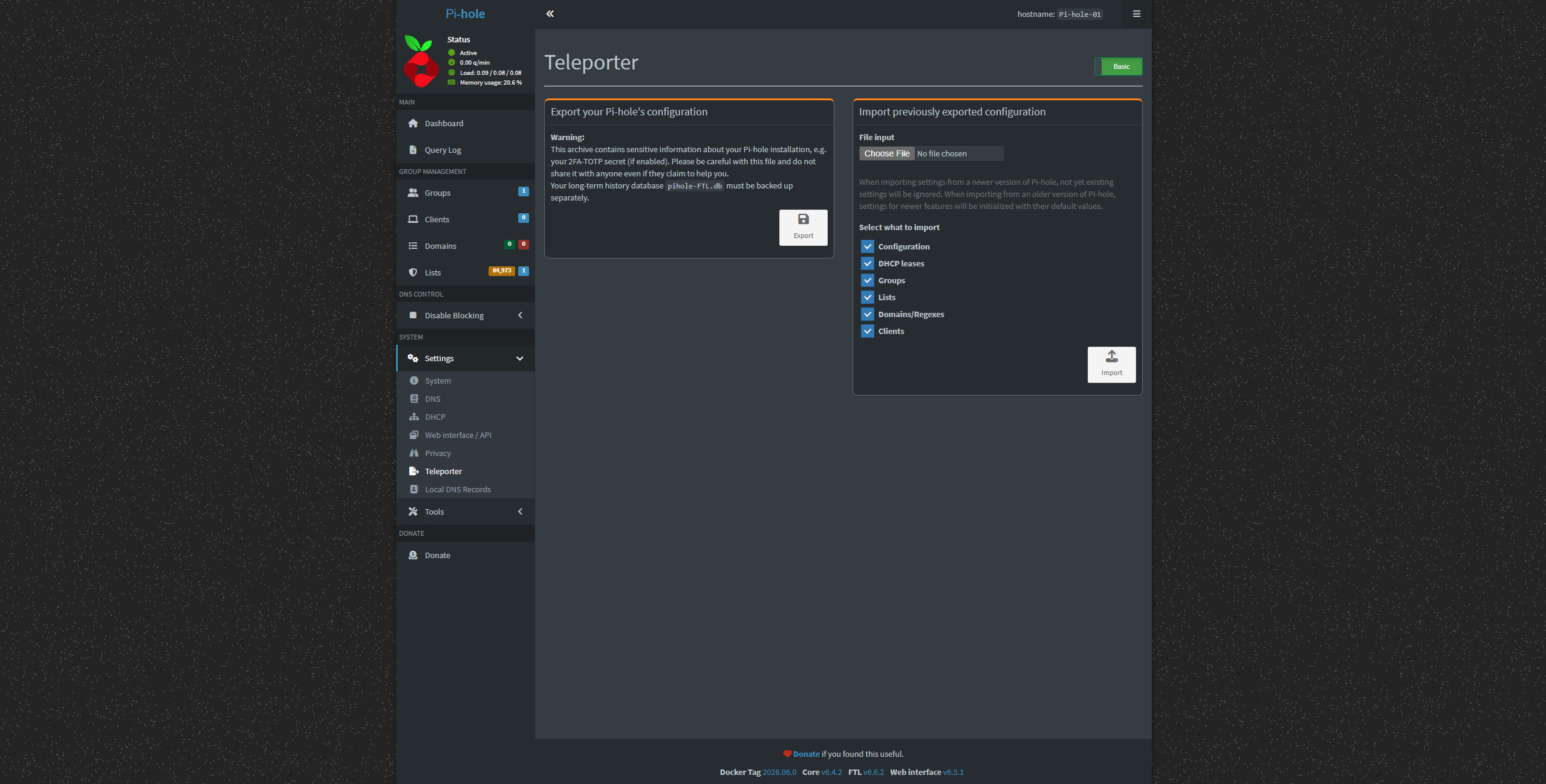
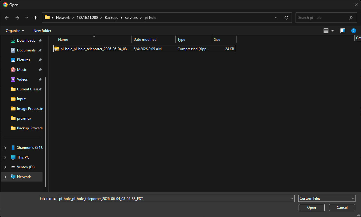
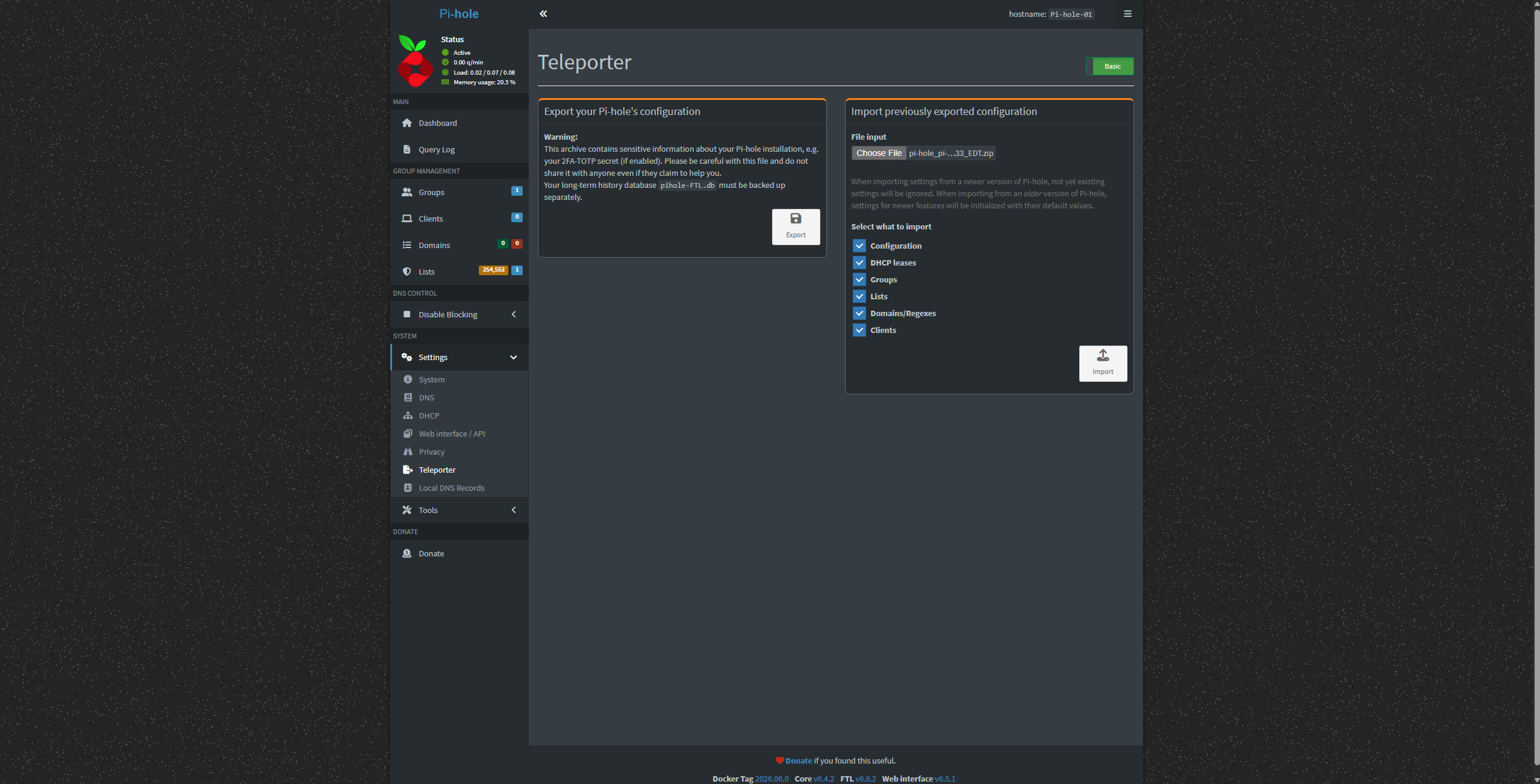
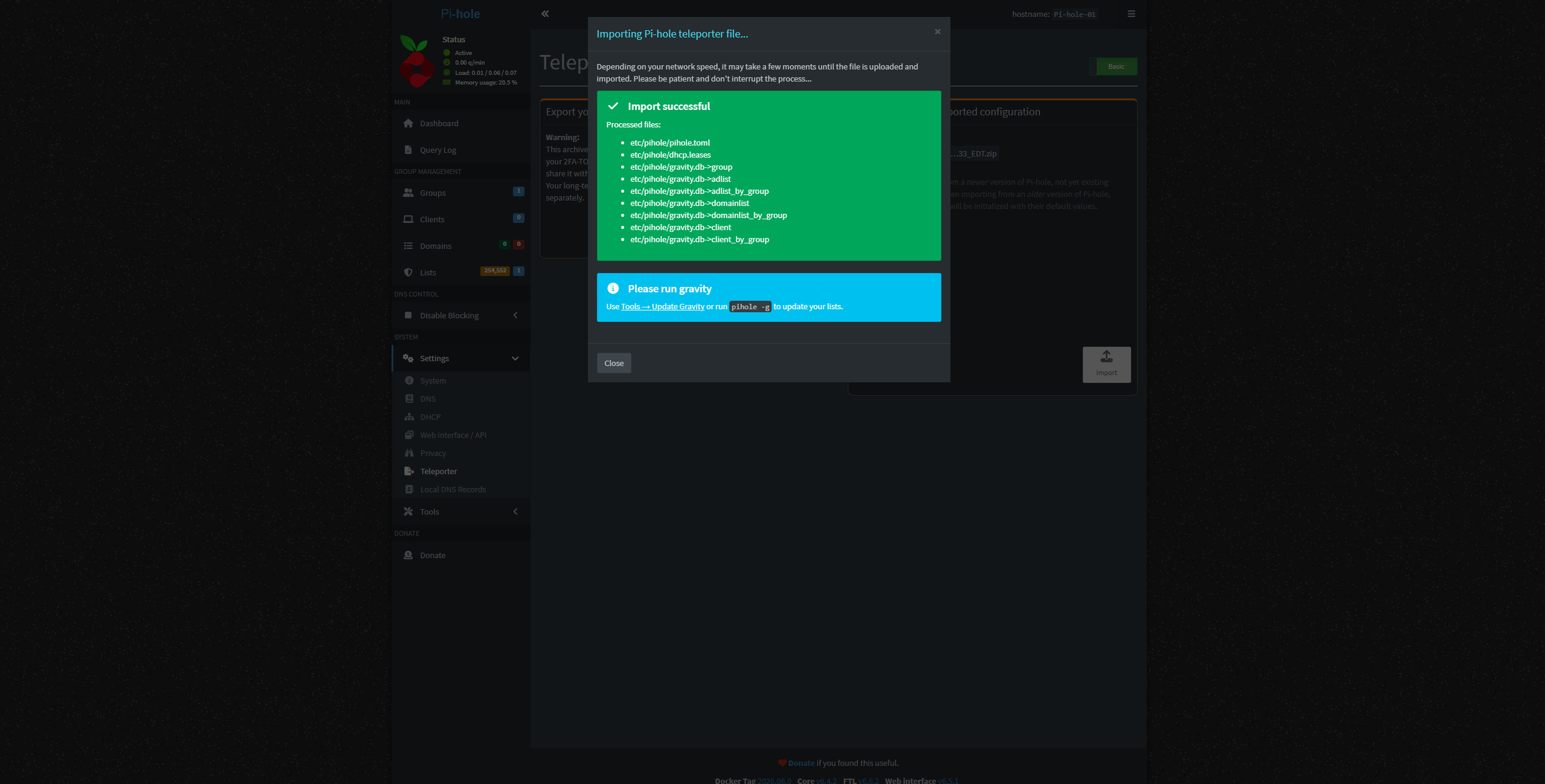
After deployment, I opened the Pi-hole dashboard, logged in, and imported a Teleporter backup from the interim Pi-hole server.
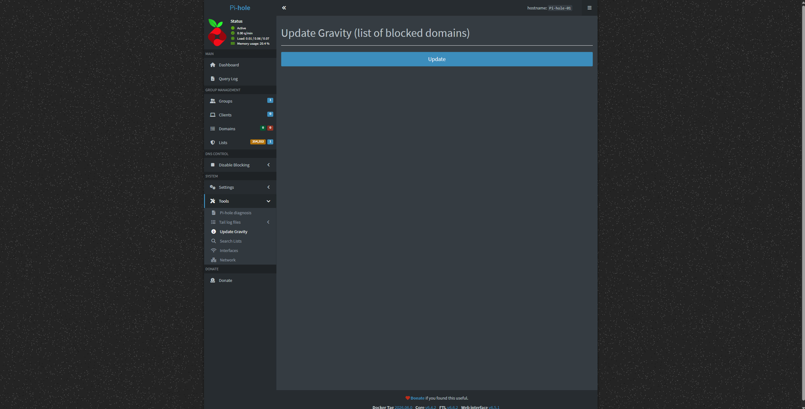
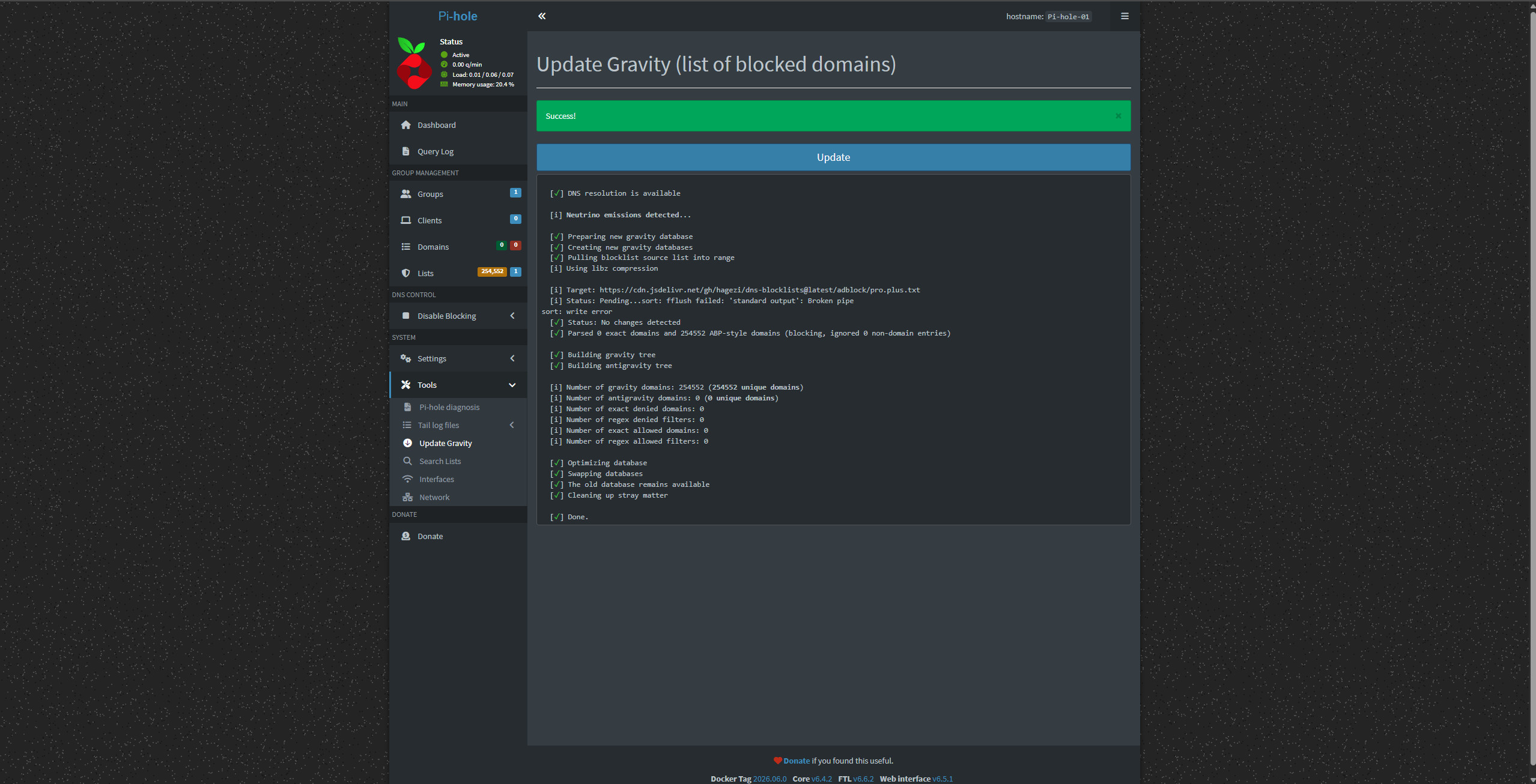
After importing the backup, I updated gravity so the imported configuration would fully apply.
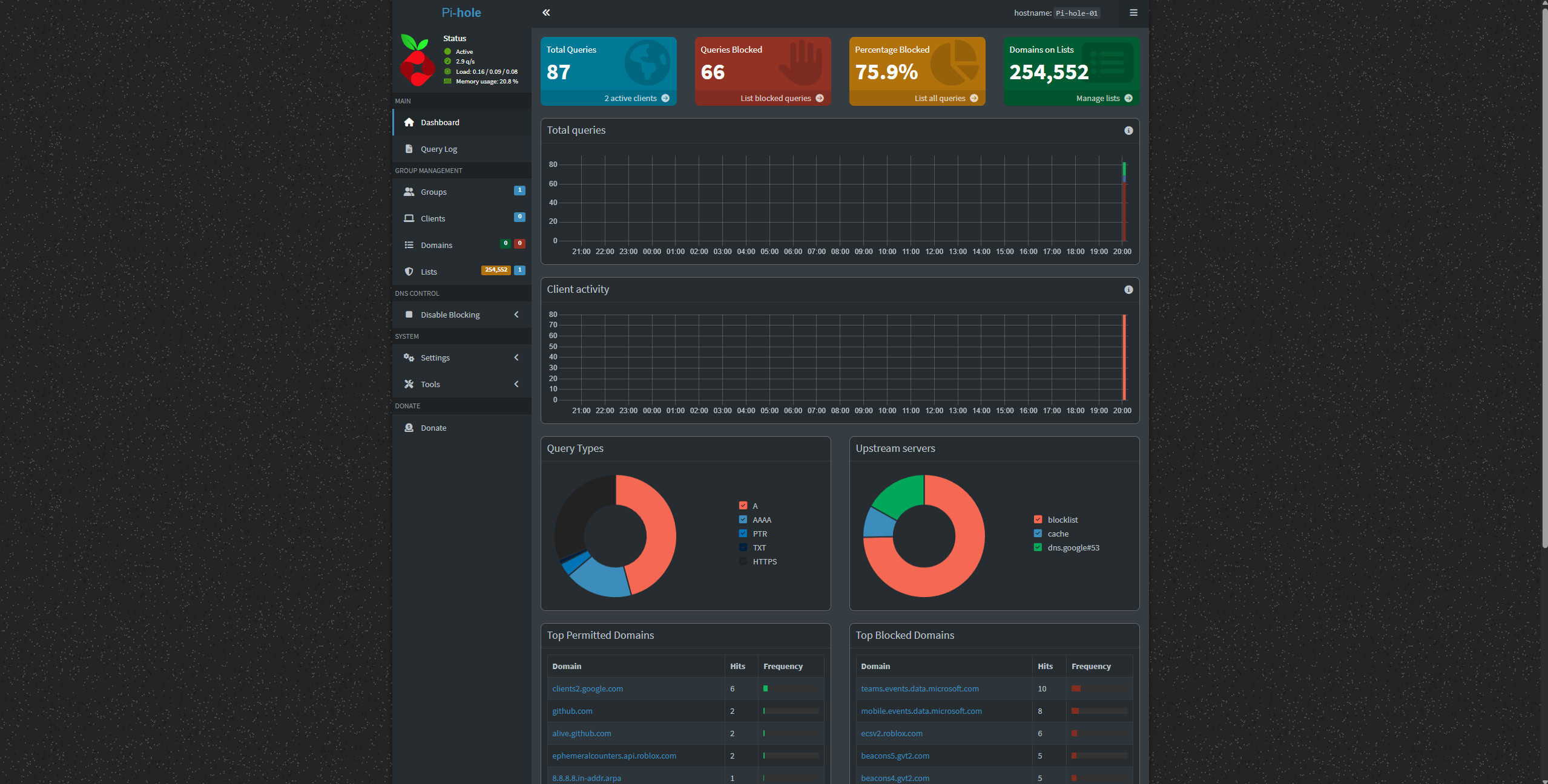
At this point, the first new Pi-hole instance was online.
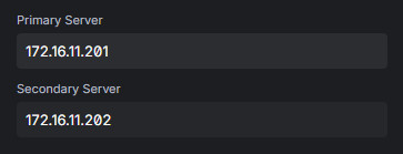
Pi-hole-01: 172.16.11.201I added it to the UDM SE as a secondary DNS server so it could begin serving DNS alongside the existing interim Pi-hole.
Rebuilding the Interim Pi-hole as wyse02#
Once Pi-hole-01 was working, I moved on to the old interim Pi-hole box. This system became wyse02.
I deconstructed the old Pi-hole server, removed its original drive, and installed another 256 GB drive. I wiped the previous drive so it can be reused later if needed, although its small size makes that unlikely.
Then I repeated the same process used for wyse01.
I installed Proxmox VE, configured the node identity, updated the switchport layout sheet, updated the device table, and added physical labeling for the new node.
The second Pi-hole instance followed the same naming and numbering pattern:
Node: wyse02
Pi-hole container: Pi-hole-02
Pi-hole IP: 172.16.11.202
Container ID: 202
Once wyse02 was online, I updated the device table with the new hostname, IP assignment, and MAC address information. I also removed the old interim Pi-hole entry from the active device list since it no longer exists in that role.
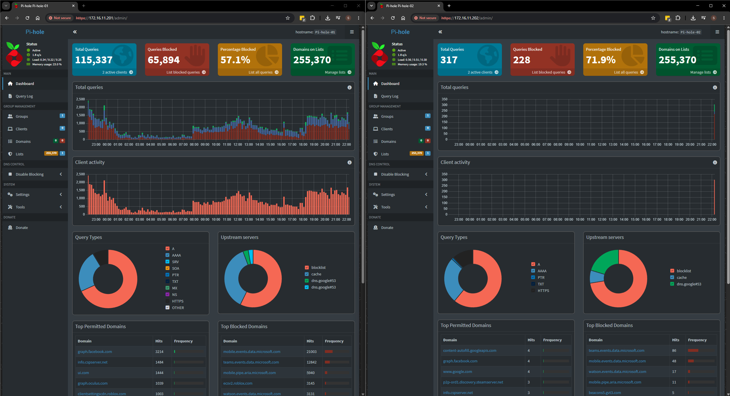
After the second DNS server was online, I took new Pi-hole backups for both instances and labeled them appropriately. I also validated that the cluster nodes could ping each other after updating all /etc/hosts files to include all nodes.
127.0.0.1 localhost.localdomain localhost
172.16.10.240 home.lab.shannonwetnight.com home
172.16.10.241 wyse01.lab.shannonwetnight.com wyse01
172.16.10.242 wyse02.lab.shannonwetnight.com wyse02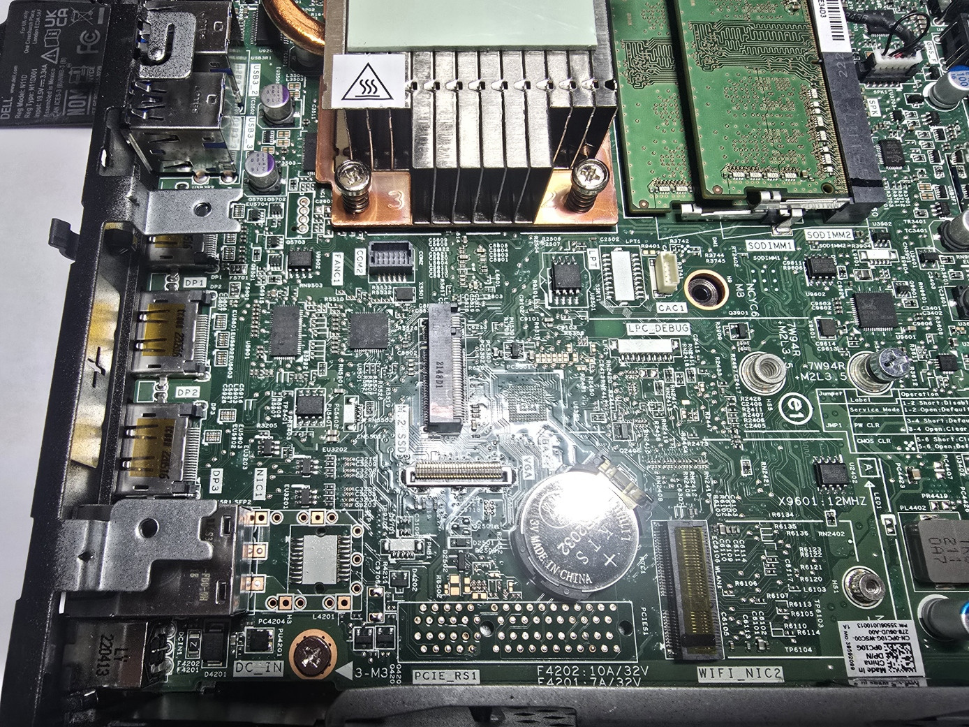
Current Status#
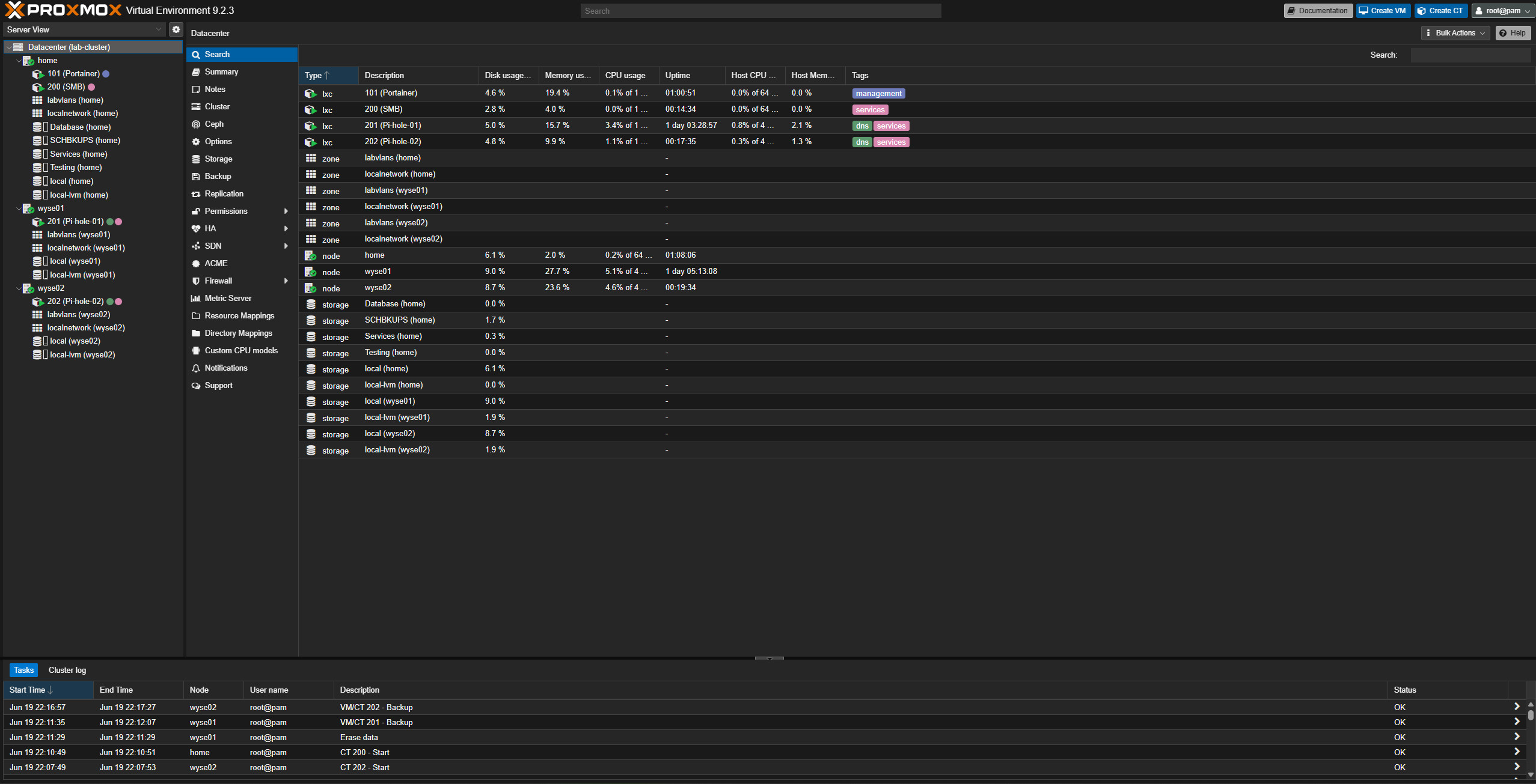
At the end of this work, the lab now has a functioning mini Proxmox cluster and dual Pi-hole DNS running on low-power hardware.
The current layout is:
home.lab    172.16.10.240  Main Proxmox server
wyse01.lab  172.16.10.241  Low-power Proxmox node
wyse02.lab  172.16.10.242  Low-power Proxmox node

Pi-hole-01  172.16.11.201  DNS server on wyse01
Pi-hole-02  172.16.11.202  DNS server on wyse02
This is a major improvement over the temporary design. DNS is no longer tied to one interim thin client, and it’s no longer dependent on the main server. The main server is the largest power draw in the rack and is the first system that should shut down during an extended power outage. If DNS lives only on the main server, basic network behavior would be affected when the server shut down. Now that I’ve moving DNS to two low-power Wyse nodes, the network can continue to resolve DNS even when the main server is offline.
The main server can focus on heavier workloads like Nextcloud, Plex, databases, media services, and future lab projects. The Wyse nodes can handle the services that should stay available for as long as possible during an outage.
Reply by Email